We put on few additional wire shortcuts on the PCB. We built in 5.6V bipolar supressor on place C30 capacitor. No more modification is necessary.
4. FUNCTION and VOLTAGES of display unit connectors.
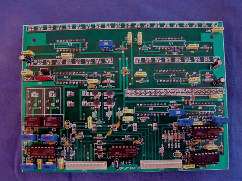
DISPLAY UNIT
1. CONTROL of the display unit.
To easy installation remove the unit from the PA: Unscrew the bottom
and the top
cover at the first. Remove the grid plate from the right top side of
the
amplifier. Unscrew the 4 screws from the frontpage. Unscrew the 3
screws from
the display panel and remove the unit.
Connect +5V to pin 8 of JP2 and +12V to pin 7 of JP2 connector from an
external
power supply.
For easy check we need a small external supply: connect 4k7 linear
potm. to pins
of 9V battery. We will have a cheap and easy PS to check the functions
of the LED
bargraphs. (If you have another DC PS you can use it for the tests)
Connect a jumper to RESET coonector pins and put please 2k2
resistor to
the pin 11 of the JP1 connector and to the ground.
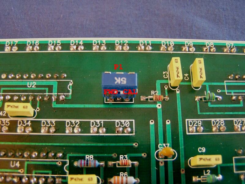
(FWD input)
a./ RF out bargraph
Set our small external PS to +1.5V out and connect the
middle pin
of the poti to
pin 11 of the JP1. If the FWD RF out meter works properly the first or
second yellow
LED will lit on RF out bargraph. We can set the RF meter
sensitivity with P1 (5K)
poti on the panel.
If everything is OK, we will calibrate the RF meter later with help an
external
power meter.
b./ RFL pwr bargraph
Connect our small PS to pin 4 of JP2 connector. Set +0.8V with
poti
before. Few green LEDs will lit now on RFL bargraph. Set now
the input voltage till the first red LED will lit on the bargraph. We
will calibrate
now the fault level of the RFL bargraph with the P2
poti.
Set the P2 poti until the RFL fault LED will blink. We will see on the
indicator
led D68 when the RFL protection will active.
Please reduce the input voltage with the PS poti and try set up again
to check
the correct level of the led bargrap and the protection level. (We can
reset
the RFL leds if we removing the jumper from the reset connector for
short time..)
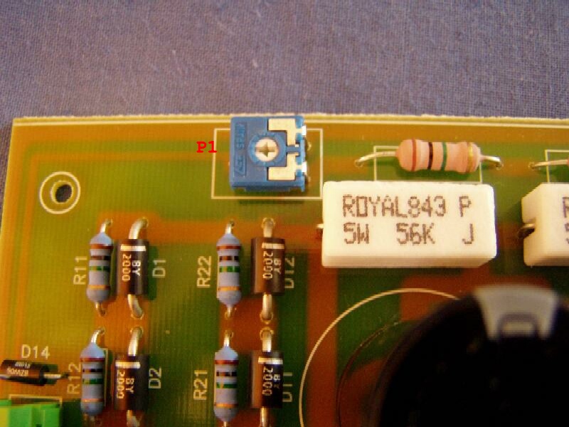
c./ Ua (HV) meter bargraph
Set please our external small PS to +2.5V output. Set please the P4
poti
full right clockwise position on the display unit.
Connect the small PS to pin 5 of JP2 connector. Push the HV red knob on
the
panel. Most of leds will lit on the Ip/HV bargraph.
We calibrate the HV meter with P1 poti
later when the unit in the PA: Have to set
the P1 up to full scale(3KV)
d./ Ig1 grid 1 current bargraph
Set the small PS to +1.5V out and connect it to pin 5 of JP2
connector.
About full leds will lit on the Ig1 bargraph now. Reduce the input
voltage set
up to first red led position.
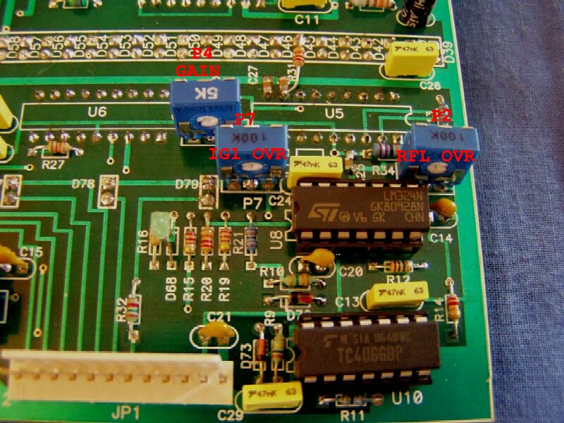
Now we will set the G1 current protection level to 350mA: Set up
please the P7
poti up
when the D67 inner led indicator start to lit.
The G1 red fault led will blink also. The Ig1 current protection set is
ready
now. (On case small PA's we can set the overload level to
smaller current level than 350mA. Set for 200mA for single GI7B or
GI46B PA's.)
We can calibrate the Ig1 meter with P3(Ig1) poti on UCU-01 unit.
e./ TMP or Ig2 current bargraph
This bargraph has two functions: sign TMP (out air temperature)
on case
triode PA's, or G2 current level by tetrode amplifiers.
If the display unit is used to tetrode PA's the resistor R22 is built
in(120k)
and the panel jumper below of pins 6-7 of U9 LM324 IC
is open. This jumper is ON on case triode PA's the R22 is missing.
Sets of triode PA's TMP:
Set 2.3V on our small PS and connect it to pin 2 of JP1 connector. Push
please
the TMP knob on the display unit. Most of led's will indicate on TMP
bargraph.
Reduce the input level up to first red led(75C). Set now the
temperature
overload level with P3 poti on display unit. The D65 small indicator
led will
sign the OVR limit. Set fine the P3
to 75C proper overload limit.
Sets of tetrode PA's IG2 current:
We need negative input voltage to check the Ig2 bargraph. So please
change
the outputs of our small test PS: please put the positive output to the
ground.
Set -1.5V output voltage with the poti and connect it to pin 2 of
JP2 connector.
Push the IG2 black knob on the display unit. Some leds will lit on the
IG2
bargraph. Set it up to recommended max. Ig2 current level. (35mA for
example on
case GU74B and GS23B tetrode amplifiers.)
Set now the overload limit with P3
poti on the display unit. We can calibrate of
bargraph sensitivity by P6 poti. The D65
on panel will indicate when we have the
necessary overload limit.
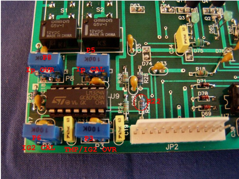
f./ Ip current bargraph
Finally we will set up the Ip bargraph meter.
We will give -9V input voltage to pin 3 of JP2 connector. Most of
leds will
lit.
We can set the sensitivity of the Ip bargraph with P5 poti
on the display unit. We can calibrate the Ip meter also with P5.
We can set full leds sign with the PS poti. Set now the 1A overcurrent
limit
with
P8 poti
on the display unit. The D66 small led will indicate it.
3. MODIFICATION on the display
unit
We put on few additional wire shortcuts on the PCB. We built in
5.6V
bipolar supressor on place C30 capacitor. No more modification is
necessary.
4. FUNCTION and VOLTAGES of display unit connectors.
JP1 CONNECTOR
| PIN | FUNCTION | VOLTAGE | WIRE COLOR |
| 1 | QRO-LED | 1.5V when ON | BROWN |
| 2 | WAIT-LED | 8.2V when BLINK | RED |
| 3 | RDY-LED | 1.5V when ON | ORANGE |
| 4 | AIR1-LED | 2V when ON | YELLOW |
| 5 | AIR2-LED | 2V when ON | ORANGE |
| 6 | OVR-LED | 8.2V when BLINK | BLACK |
| 7 | ON-LED | 12V | - |
| 8 | N.C. | - | - |
| 9 | N.C. | - | - |
| 10 | N.C. | - | - |
| 11 | FWD-input | 0-2.5V | DIFFERENT |
| 12 | GND | 0 V | BLACK |
JP2 CONNECTOR
| PIN | FUNKTION | VOLTAGE | WIRE COLOR |
| 1 | GND | 0 V | BLACK |
| 2 | TMP | max 2.2V | YELLOW/WH |
| IG2 | -1.8V | GREEN/ | |
| 3 | IP | -10V max | BROWN/WH |
| 4 | RFL | 2V max | DIFFERENT |
| 5 | IG1 | 0-1.5V | BROWN |
| 6 | Uameter | ~ +2.5V | BLUE/WH |
| 7 | +12V VCC | +12V | BLUE |
| 8 | +5V VDD | +5V | RED |
| 9 | FAULT/OVR | +2.6V when fault | GRAY/WH |
| 10 | N.C. | - | - |
| 11 | N.C. | - | - |
| 12 | N.C. | - | - |
Mechanics & Electronics Inc. 1991-2023 All rigts reserved.