2017-09-09
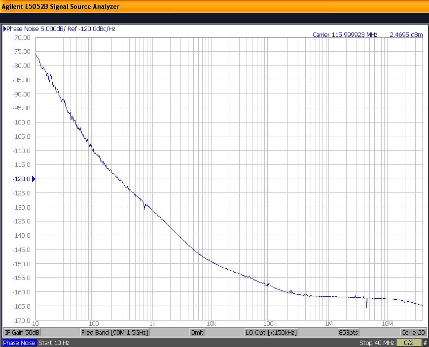
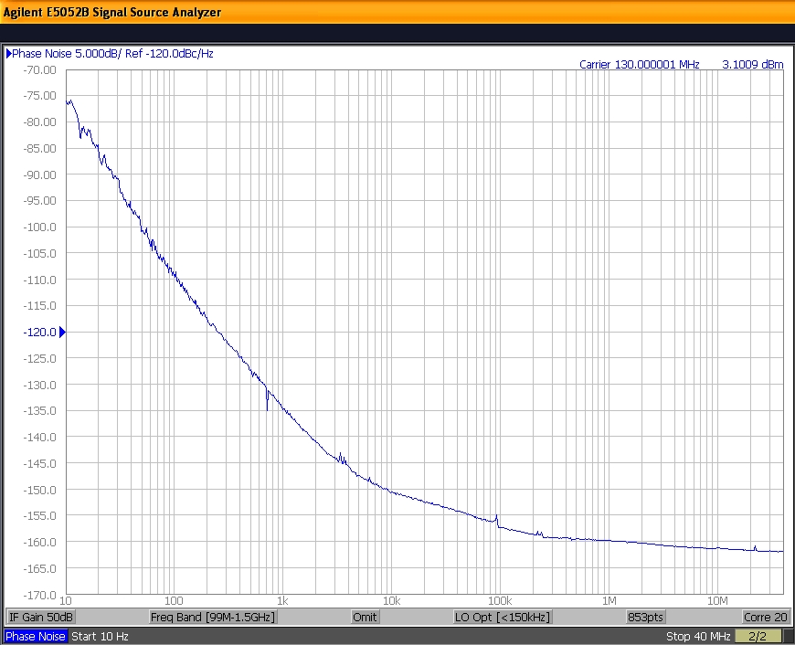
The measured TCXO phase noises: PDI
AXTAL 116MHz phase noise: AXTAL 130MHz phase noise
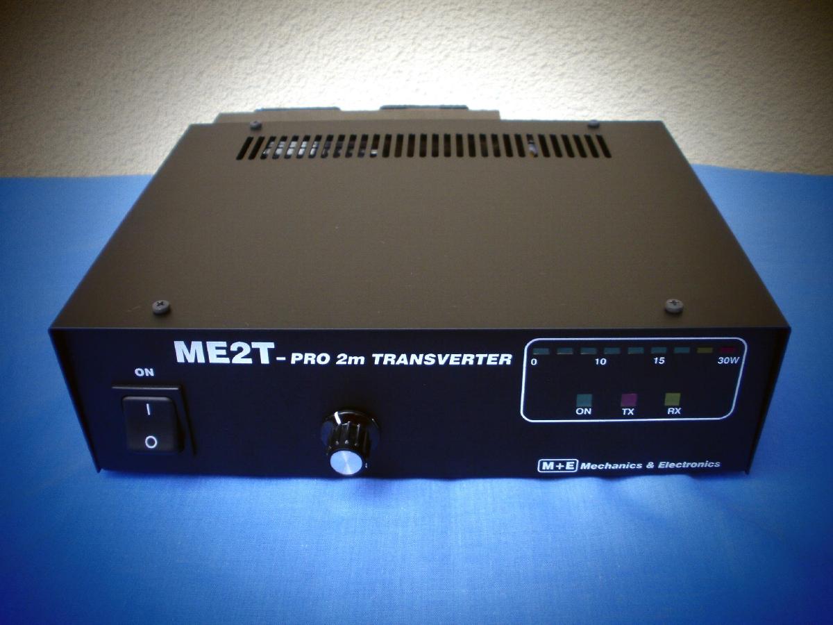
ME2T-PRO-II
High Performance 2m transverter
After the successful ME2T-PRO transverter project we decided to
modify the -PRO version.
We built in the best Mini Circuits dual
ballanced mixer the HJK-3H. The new built in IF amplifier (ASF240
from ASB) has low noise, combinated with very good dinamic range on
receiving section.
You can find the block diagram of the base
100mW transverter unit
here.
The built in military class low phase noise TCXO
provide easy work also on digital modes.
Optional AXTAL
0.5ppm TCXO also available!
The
transverter can work between 144-146MHz with low RX NF and high
OIP3.
The Mitsubishi RF module provides good IMD signal and 30W
output power.
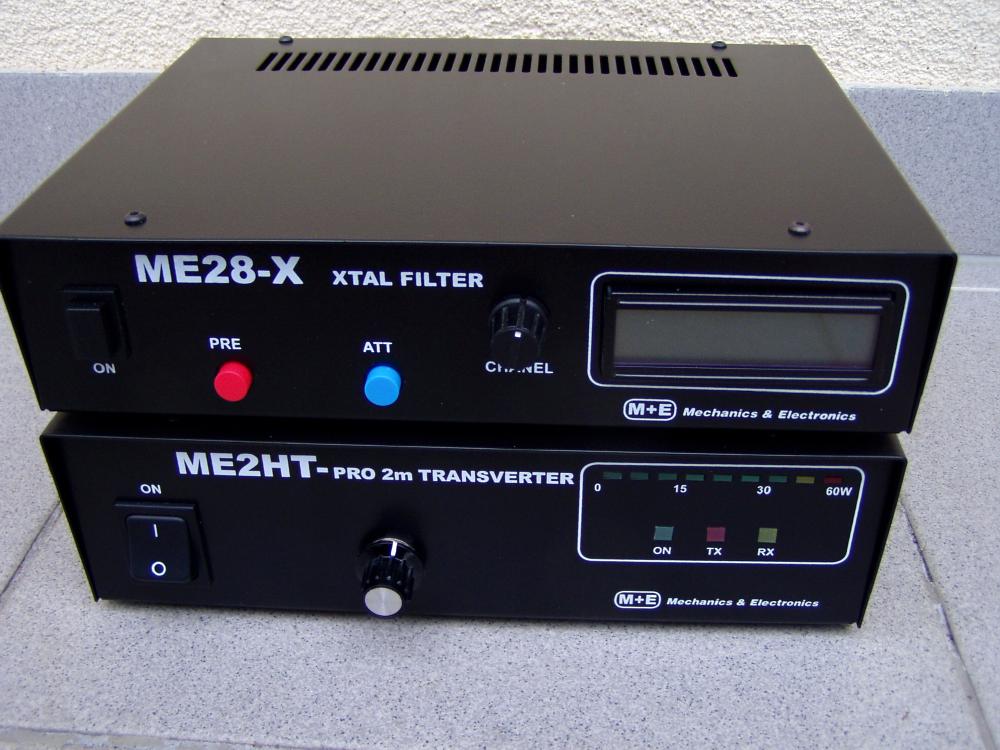
The ME2HT-PRO-II basically same as ME2T-PRO-II but
furnished with 80W RF module.
Before of first operation, check
the setup description.
Local
Oscillator
The high stability TC23-5T
type TCXO by PDI (+/-1ppm btn 0-50 degr. C) with
low phase noise gives +3dBm signal on 116.000MHz (or on 130MHz).
The
TCXO frequency can be adjusted with inner trimmer capacitor (+/-2ppm)
but it's not necessary because the stability is better than
+/-1ppm/Year.
TCXO stability and the phase noise is better than
most modern transceiver's phase noise.
The output signal of the LO
is about +23dBm, it produced by pair of ASB ASL550
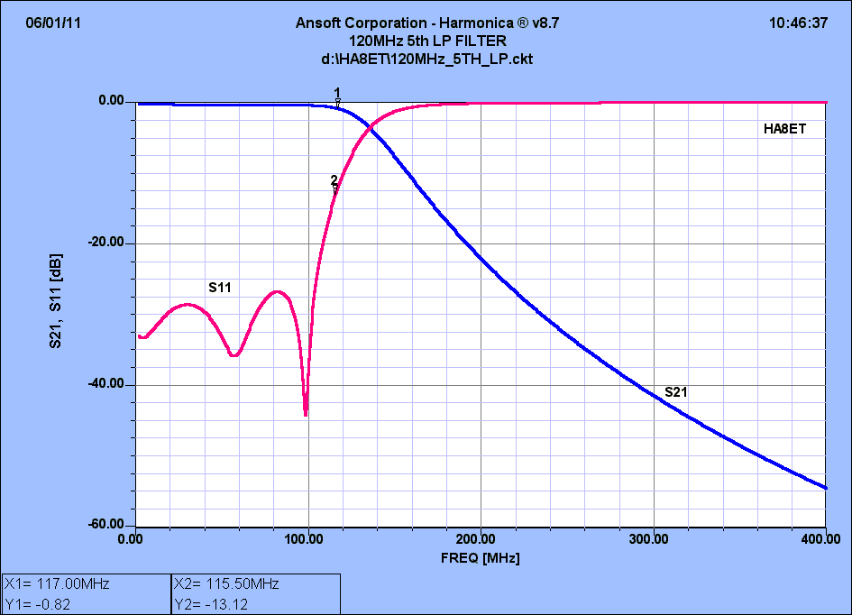
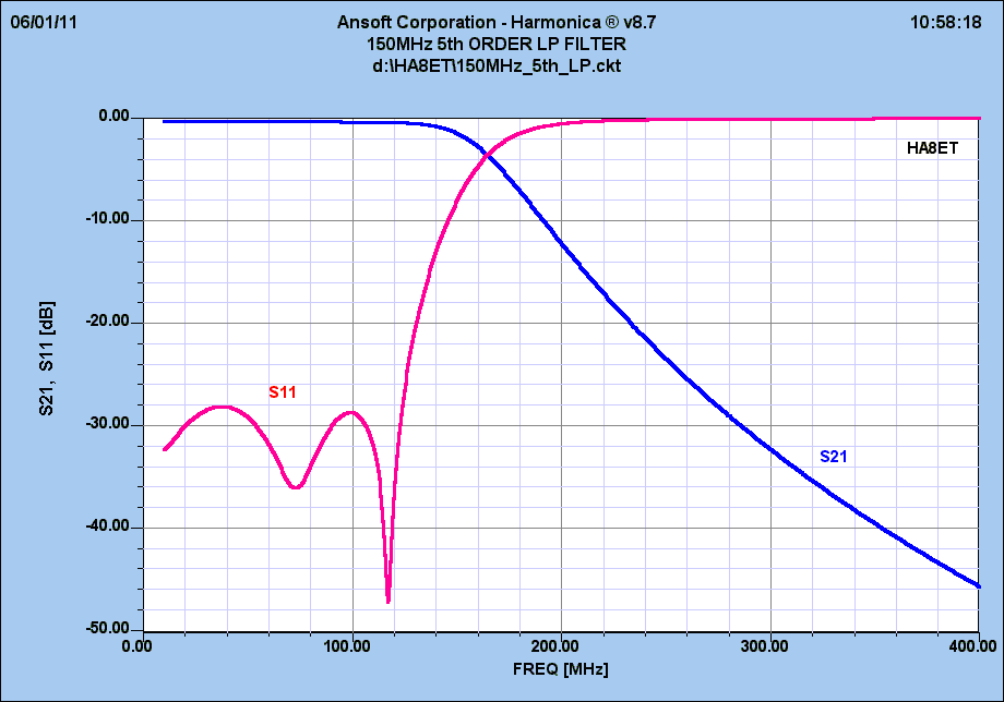
3rd generation MMIC. The built in 2x 5th order filter provides clear
output signal.
The simulated
caracteristics of the 5th order 120MHz LPF filter:
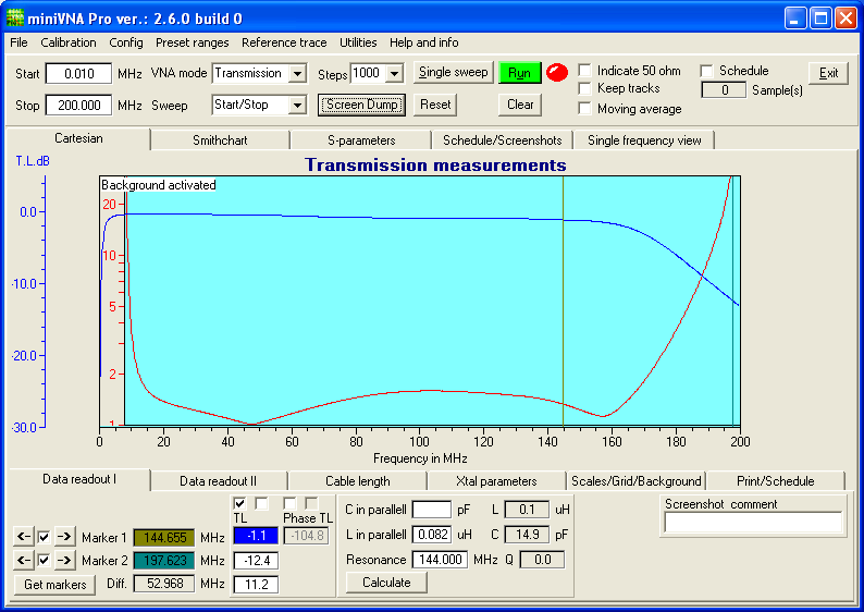
The
measured TCXO phase noises:
|
|
|
|
|
|
We
can check the +23dBm output signal on M3 measuring pin. This signal
is attenuated by -10dB to the TX balance mixer (CSYM-1815).
We are
using HJK-3H+
type (+37dBm IP3) mixer in the RX side. We can
check the real RX and TX LO signals on M2 and M1 points with DC
voltmeter.
RX/TX
The
144-146MHz input signal passes through the input filter to the input
PGA103+ LNA. The gain is approx. 20dB, the noise figure is 0.7dB, the
OIP3 is >30dBm! PGA103+ has an exceptional performance of low
noise figure, high gain, high OIP3, and low bias current.
The
stability factor is always kept more then unity over the application
band in order system environment.
Impedance of the MMIC is 50 Ohm
both I/O - it provides easy connect on the output 3rd order
BPF.
PGA-103+ produces about +9..10dBm IIP3!
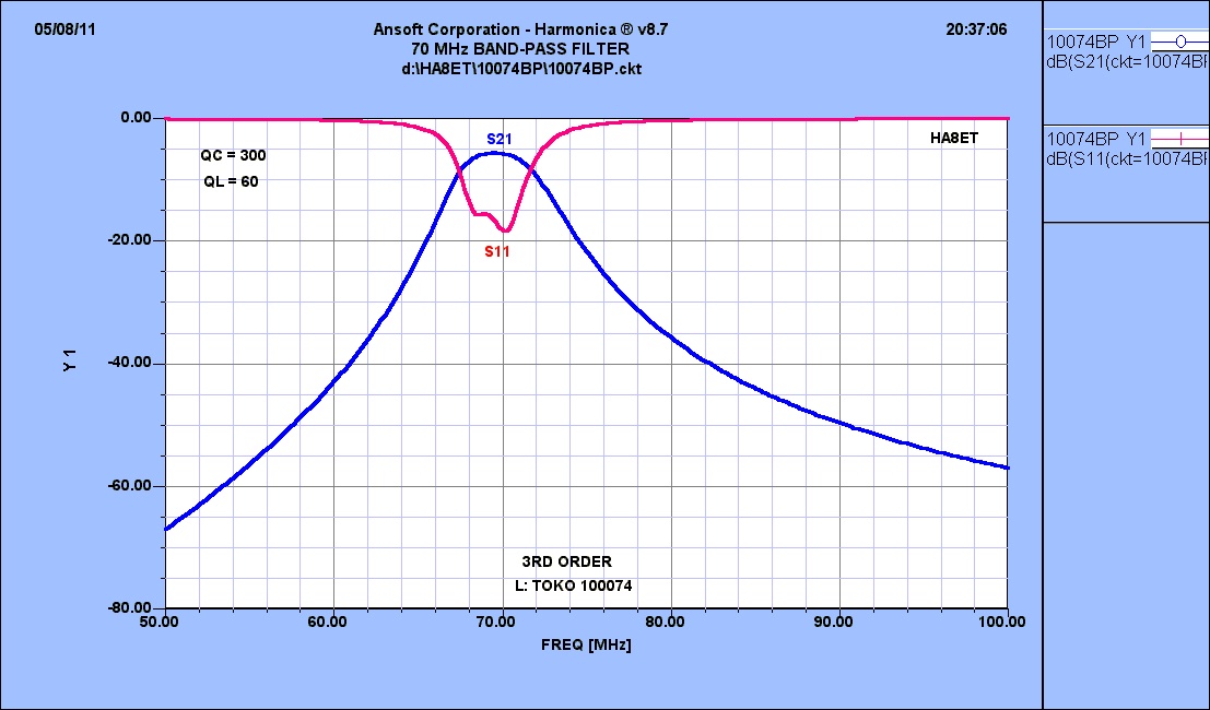
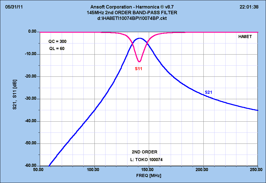
The
characteristics of the 3rd order BPF:
|
|
|
The
144-146MHz signal goes through the band pass filter providing a
suitable selectivity.
The balanced mixer MX1 mixes the input
signal down to 28-30MHz (or 14-16MHz) loosing approx.
6 dB in the
process. The IF signal is amplified by approx.17dB in a low noise,
high dinamics ASB ASF240 IF amplifier.
The final PI filter
increses the selectivity considerably. The output signal is can set
to optimal value
with the RX gain
potentiometer.
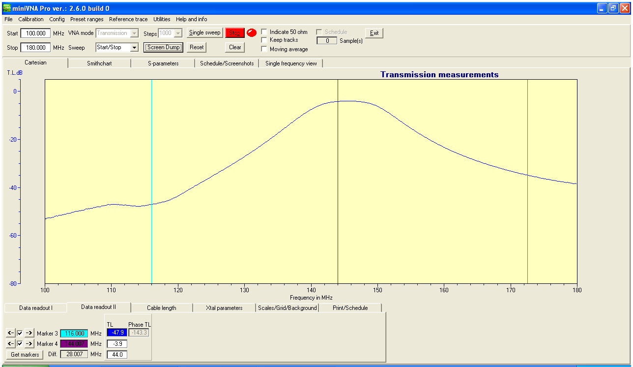
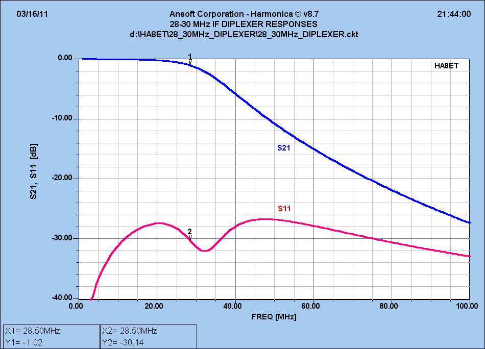
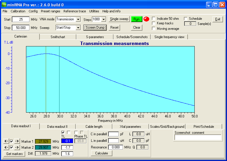
Measuring
of diplexer and 28MHz LPF unit:
|
|
|
Diplexer full simulation
The transmit mixer, MX2 only needs approx. -10dBm 28
MHz IF signal from the transceiver. A suitable level can be achieved
by adjusting P2(TX) in the attenuator. Lot of transceivers has lower
or much higher IF output level. To solve this problem we built in an
additional jumperable and variable 5W/-20dB attenuator. You can
switch on/off easy the attenuator with different jumpers.
The fine
level setting possible with the potentiometer P1 on the attenuator
unit across the slots of the top cover.
We solved very low level
IF out problem of most ICOM radios (-20dBm).
We built in +15dB
gain jumperable IF
amplifier so ME2T-PRO-II is usable easy to this radio
types.
The 144 MHz TX signal behind the MX2 mixer is filtered
through a three-stage band-pass filter before being amplified in a
BF966.
Simulated characteristics of the 3rd order BPF:
|
ME2T-PRO spectrum: ME2T-PRO_spectr (pdf)
|
The G2 of the BF966 connects to the ALC circuit on the control
unit and to the rear panel PWR potentiometer. We can reduce the final
output power to about 5-6Watts.
The controlled gain BF996
amplifier continues the final ASL550 amplifier to a level exceeding
more than 100 mW. Through the final pi-filter we can reduce the
harmonics of the TX signal.
|
|
|
:
2m
module PA unit
We constructed >25W output
amplifier to the base transverter unit. It's built with RA30H1317M
Mitsubishi module, by Mitsubishi datasheet and applications.
The
output signal of the transverter drives the RF module across -3dB
attenuator. We set the RF
module to AB1 class by a simple circuit
applicated by Mitsubishi.
The ME2HT-PRO-II model PA contains
RA80H1415M type 80W RF module.
The output signal led to "N"
type 2m ant connector across a harmonics filter and a built in
NEC
EB2-12NU type smd RF relay.
The final unit has MON output to check
the output power connecting to the control unit LED bargraph PWR
meter and ALC circuit.
The PA contains simple temperature sensor
to check the temperature of the heatsink.
The external heater fan
module is standard in case 50W transverters, option in case the 30W
model.
CONTROL UNIT
In
order to monitor output power, we use an LM3419 based LED bar graph,
implemented on the DP6 control unit. You can find the high current DC
relay too on this PCB, together with the ALC circuit and the circuit
of the external fan speed regulator. The external (optional) fan's
speed is reduced by 50% during RX state.
In case of long TX
periods, when the final PA module's heatsink temperature exceeds
normal, than the circuit increases the speed of the DC fan. The speed
depends on the heatsink temperature. We can calibrate the normal fan
speed with the P2, the ALC level with the P3 potentiometer.
The
LEG-12 relay is switching the Vpp voltage to the PA unit. The
calibration of the output power on
the bargraph, is possible with
P1 pwr poti on the DP6 unit.
Switch/attenuator
panel
People use different IF level
transceivers from home or / portable operation. The jumper selectable
attenuator solves the problem; let it be either high or low level IF
signal transceiver.
You can either set ON or OFF the 5W
attenuator, what is more, you can also easily choose single or
dual
cable IF operation with these built in jumpers.
The unit contains
switching circuit associated to the external PA's (red colour RCA,
SND output,
(capable to switch max +50V,1A).
The
PTT circuit uses two MJD127 devices on the transverter unit for the
RX/TX switching.TX when the PTT is grounded.
The PA circuit
includes a sequencer, providing suitable delay in the TX key signal
when activating first the relays of the external PA relay, then the
antenna relay and RF module first stage of the transverter. This
means that the TX output is delayed approx. 50 ms after then antenna
relay is activated.
The antenna relay of the ME2T-PRO and the
external PA switches without any TX signal present.
Position of built in attenuator jumpers
|
Low PWR IF input |
Low PWR IF input |
|
|
J1 |
ON |
ON |
|
J2 |
OFF |
ON |
|
J3 |
OFF |
OFF |
|
J4 |
OFF |
ON |
|
J5 |
ON |
OFF(ON- 2nd RX) |
|
High PWR IF input (27..+37dBm) |
High PWR IF input (27..+37dBm) |
|
|
J1 |
OFF |
OFF |
|
J2 |
ON |
ON |
|
J3 |
ON |
ON |
|
J4 |
OFF |
ON |
|
J5 |
ON |
OFF (ON-2nd RX) |
If you use single IF cable between your radio and the
transverter, you connect it to transverter IFin BNC.
In this case
the IF-out connector is not in use. If you want to use a 2nd (e.g.
SDR) RX, then switch J5 into ON state. (Only in case of single IF
cable mode!)
Don't forget to connect
the PTT cable between radio SND connector and ME2T-PRO PTT input!
Otherwise the IF power (5W) kills the
transverter IF output part (single IF cable high IF power version).
The output is protected by antiparallel diodes but it does not help
in case high IF power!
Never apply more than 5W IF level to the
attenuator!
In order to protect the RX of those who
forget to connect the PTT line, we built in an IF RF VOX circuit in
the new version.
The RF VOX interacts at an IF level exceeding
+27dBm, but only in case single IF cable mode.
Construction
The base transverter is built on a 1,5 mm double sided glass-fibre
epoxy PCB; it is fitted into a standard metal sheet box measuring 148
x 74 x 30mm.
PA unit is fitted into 148 x 55 x 30mm standard box.
Both are manufactured with SMD technics.
The external box of the
transverter is constructed from 1mm painted iron plate. The heatsink
is 150x55mm ALU heatsink material.
If you use the ME2T-PRO
continuously on FSK mode you can order optional
fan module (2pcs 50x50mm DC fans on holder plate).
No
overheating problem occours in case normal room temperature while
operating on CW, or SSB and contest mode.
You can find on the
front panel the ON/OFF switch, the LED bargraph power meter the PWR
potentiomter. The latter reduces the output power to a desired level,
down to to 5-6 Watts to drive an external FET PA's.
High
performance contest station with ME14-X or ME28-X RX/TX
crystal preselector:
TECHNICAL
PARAMETER
|
Frequency range |
144-146MHz |
|
IF frequency range |
28-30MHz or 14-16MHz |
|
Emission modes |
CW,SSB,FM,Digital |
|
I/O impedance |
50 Ohm/unbalanced Ant-"N" type, IF 2x BNC |
|
Operating temp. range |
0-+50C |
|
LO accuracy @ 20C |
1ppm PDI TCXO, <0.5ppm on AXTAL TCXO |
|
LO accuracy @ 0-50C |
+/-1ppm PDI TCXO (+/-0.5ppm with AXTAL TCXO) |
|
Input voltage |
13.8V +/-5% |
|
Power consumption |
0.48A on RX, 5.5A/TX (10.5A, ME2HT-PRO-II 50W) |
|
IF power input |
-20...+37dBm |
|
IF input VSWR |
1:1,1typ, max 1:1,3 |
|
Output PWR |
ME2T-PRO-II=30W, ME2HT-PRO-II=50W variable |
|
TX harmonics |
min. -60dB |
|
IM3 |
-33dBc/ 25W output, or 50Watt output (HT version) |
|
PTT control |
Contact closure to GND |
|
SND output |
Open collector, +50V/1A max. |
|
RF VOX |
Available, starts >27dBm IF input |
|
RX noise figure @ 20C |
1dB (overall) |
|
RX gain |
max 25dB (variable) |
|
RX OIP3 |
typ. +35dBm, min. +30dBm |
|
RX IIP3 |
typ. +10dBm, min. +8dBm |
|
Image rejection |
>85dB |
|
Dimensions |
240x260x70mm (incl. optional fans) |
|
Weight |
1.6kg |
Mechanics &
Electronics Inc. All rights reserved. 2017.