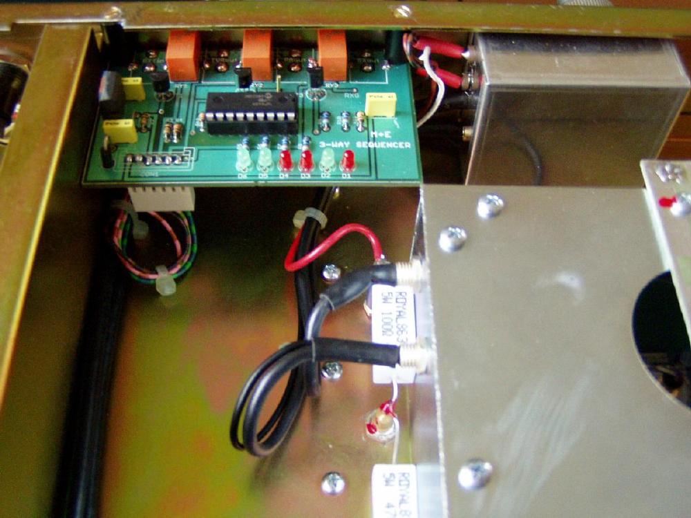
Building in 3-way PIC controlled seuencer in the old PA models.
We
building in new 3-way PIC controlled sequencer from
2009 Jan. in every VHF and UHF models.
You can build in the sequencer easy in your old model.
Please drill 3 pcs 9mm dia holes
on
the rear panel. The distance between holes is 20mm.
Please mount the sequencer PCB with two plastic holder and 2pcs 2.5mm
dia screw
to the rear panel.
If it is difficult for you, you can mount the PCB on any free place on
the
bottom side of the amplifier.
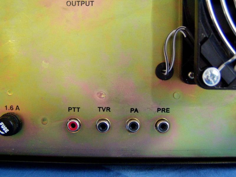
On this case you mount only new separate 3 RCA connectors on the rear
panel,
(6.5mm dia holes!!)
and you can connect them to the center output holes on the sequencer
panel with short
isolated wires.
The CON1 pins of 6 pole PCB connector of sequencer:
| PIN | FUNKTION | VOLTAGE | CONNECT TO |
| 1 | UCC | +12-15V | UCU-01,JP9/8 pin. |
| 2 | GND | 0V | GND |
| 3 | PTT in | +5V RX,GND TX | PTT_in RCA (5V,2mA) |
| 4 | TCVR_GND_out | high on RX,GND TX | |
| 5 | PA GND out | +12V on RX, GND TX | pin JP3/6 on UCU-01 |
| 6 | PREAMP GND_out | high on RX, GND TX |
You have to connect the pin 1 to +12-15V, the pin 2 to the
GND, the pin5 to the
JP3/6 on UCU01 control unit.(the old PTT_in green wire).
If we installed well everything every green LED's will lit on
the
sequencer unit after switch on the amplifier.
When we put a shortcut to the PTT input RCA (red) the PRE red led
will lit at once,
the PA led after 50msec,
and finally the TVR red 3mm led 50msec later.The max load of
every
sequencer output is 60Vand 1Amper.
So the preamplifier relay will switch first, after 50msec the PA
input and
output relay, and finally the
TVR relay switches the transceiver PTT output to the ground parallel
with the PA
cathode relay.
Every RF relay will switch without RF power- it will save the contacts.
Check the proper connects of the connectors on the following drawing: